De Hammond Encyclopedie
- Orgel Uitbreidingen
- Reverb Unit voor M3
- Kit voor L en M series
- QRS Pianoroll Systeem
- Kit AO-31200-1 M 100 series
- Benson Bass System
- Benson Percussion Unit
- EIS Oakland
- Electro Tone 13
- Electro Tone Duet 16
- Electro Tone Organ Mate Reverb
- Electro Tone PER200 Percussion Unit
- Hammond Foot Pedal Extender
- Hammond 300 H Headphone 1969
- Hammond Phoenix met afspeel mechanisme
- Hamptone LEQ3B Organ EQ
- Maas Rowe Krueger String Bass
- Maas Rowe Minor Bells Carillon
- Maas Rowe Vibrachime Carillon
- Maas Rowe Company
- Selectone
- Maric Swingbeat
- Trek II
- Profkon ZD-1
- Pro-Co bakstuk
Electro Tone DUET 16
Electro Tone was een van de bekendere bedrijven op het gebied van uitbreidingskits voor de L en de M serie Hammondorgels. De fabriek stond in Santa Monica, Californië.
De controllers of te wel de bedieningspanelen maakte deze fabrikant perfect passend voor de Hammond bakstukken.
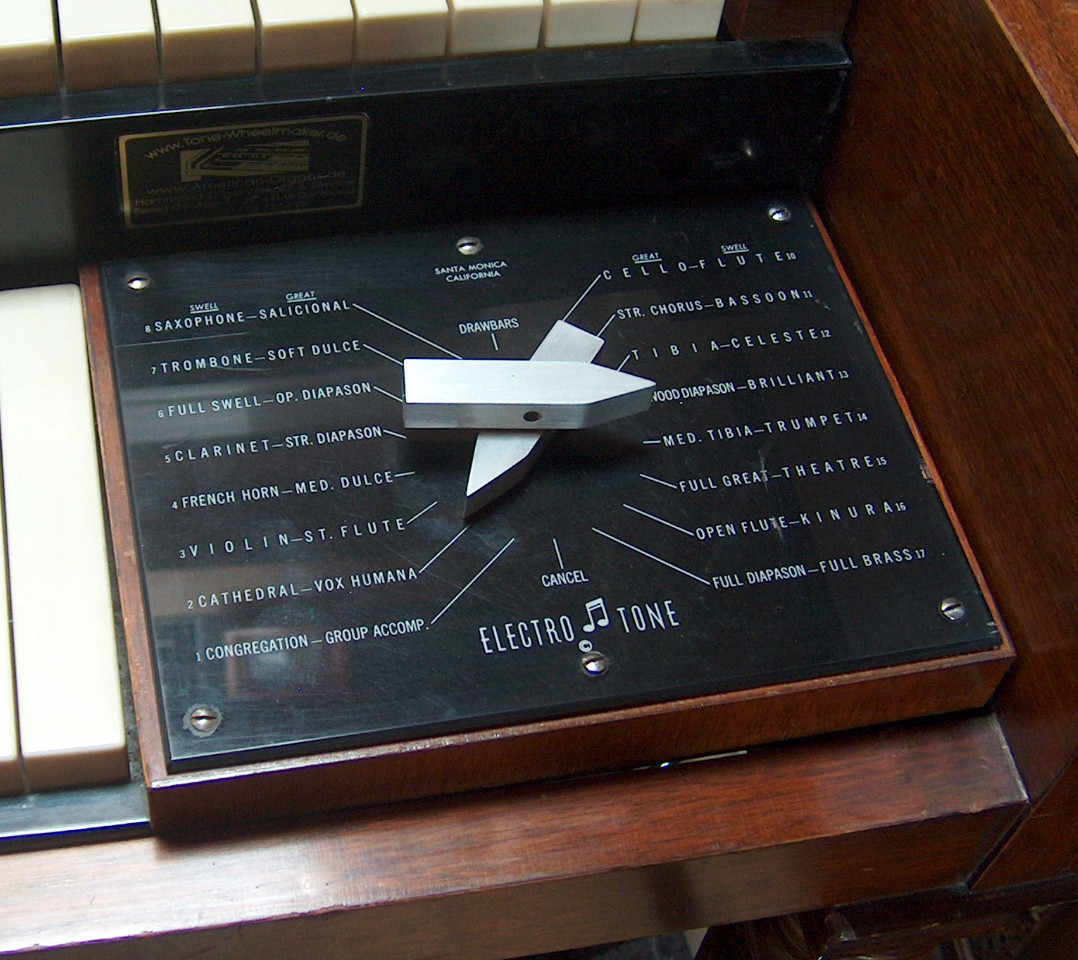
De kit "ELECTRO TONE DUET 16" bood de organist een aardig aantal extra presets.
Hij had twee op elkaar rustende draaiknoppen.
De bovenste aanwijzer bediende het bovenklavier en de onderste het onderklavier.
Daarom worden voor alle schakelaarstanden 2 presets naast elkaar genoemd:
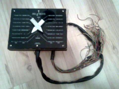
Hier de kit separaat met de kabel voor de aansluitingen:
Tot slot hieronder de amerikaanse uitleg en aansluithandleiding.
The Electro Tone Corporation was a company that produced after market add-ons for Hammond organs in the 1960s and '70s, with more than 2,300 dealers internationally.
The company manufactured the OrganMate reverb kit, PER 200 percussion kit and the Duet Sixteen and Mark II preset kits. These kits were primarily retro-fitted to Hammond organs that required reverb, percussion or presets.
The company was situated at 2014 Broadway, later at 1814-A Colorado Ave and then at 2126 Pico Blvd, Santa Monica.
Packing Contents
* 1.0 Electro Tone Duet Sixteen
* 1.1 Internal workings of the Duet Sixteen
* 1.2 Cable identification on the Duet Sixteen's rotary switch
* 1.3 Installation of The Duet Sixteen
* 2 References
Electro Tone Duet Sixteen
The DUET SIXTEEN PRESET is available for the Hammond Spinet Organ Models M, M-2, M-3, L-100 and M-100 series organs.
The DUET SIXTEEN has 16 Presets on each manual, plus the use of the Drawbars, making the possibility of 256 Preset combinations.
Suggested List... $159.50
Internal workings of the Duet Sixteen
The Hammond organ's cheek block and Duet Sixteen can be removed from the organ by removing the two screws on either side of the cheek block from underneath. When pulling the cheek block and Duet Sixteen up, be carefull so as not to put undue stress on the cable passing through to the back of the organ.
The black metal casing can be removed by unscrewing the two nuts at the bottom of the Duet Sixteen housing, the nut & bolt holding the plastic cable holder and the four flat head screws at the top of the black metal housing, nearest the underside of the cheek block.
Carefully sliding off the black metal housing exposes the rotary switch.
Cable identification on the Duet Sixteen's rotary switch:
Cable #1 (Upper Drawbars)
* 9 wires (brown, red, orange, yellow, green, blue, violet, grey, white)
* Terminals on lower rotary switch cluster.
* Terminals vertically aligned.
* Terminals adjacent to cable #5 terminals.
* Terminals directly opposite side of switch to cable #3 terminals.
* Terminals aligned directly below cable #2 terminals.
Cable #2 (Lower Drawbars)
* 7 wires (brown, red, orange, yellow, green, blue, violet)
* Terminals on upper rotary switch cluster.
* Terminals vertically aligned.
* Terminals directly opposite side of switch to cable #4 terminals.
* Terminals aligned directly above cable #1 terminals.
Cable #3 (Upper Drawbar Wires)
* 9 wires (brown, red, orange, yellow, green, blue, violet, grey, white)
* Terminals on lower rotary switch cluster.
* Terminals vertically aligned.
* Terminals directly opposite side of switch to cable #1 terminals.
* Terminals aligned directly below cable #4 terminals.
Cable #4 (Lower Drawbar Wires)
* 7 wires (brown, red, orange, yellow, green, blue, violet)
* Terminals on upper rotary switch cluster.
* Terminals vertically aligned.
* Terminals directly opposite side of switch to cable #2 terminals.
* Terminals aligned directly above cable #3 terminals.
Cable #5 (Right Side Matching Transformer)
* 7 wires (red, orange, yellow, green, blue, violet, grey)
* Terminals on lower rotary switch cluster.
* Terminals vertically aligned, except for yellow wire terminal.
* Terminals adjacent to cable #5 terminals (except for yellow wire terminal).
Cable #6 (Left Side Matching Transformer)
* 7 wires (red, orange, yellow, green, blue, violet, grey)
* Terminals on upper rotary switch cluster.
* Orange, yellow, green, blue & grey terminals vertically aligned.
* Red & violet terminals vertically aligned, and grouped with cable #4 wires.
Cable: #1 #2 #3 #4 #5 #6
Manual: upper lower upper lower upper lower
Connection: drawbars drawbars drawbar wires drawbar wires matching transformer matching transformer
wire 1: brown brown brown brown --- ---
wire 2: red red red red red red
wire 3: orange orange orange orange orange orange
wire 4: yellow yellow yellow yellow yellow yellow
wire 5: green green green green green green
wire 6: blue blue blue blue blue blue
wire 7: violet violet violet violet violet violet
wire 8: grey --- grey --- grey grey
wire 9: white --- white --- --- ---

