Percussion Tone (Hanert)
De Percussion Tone is een uitvinding van Hammond's bekende ingenieur, Trument J.M. Hanert, die vele instrumenten voor Hammond zou ontwerpen, o.a. de Solovox, de ExtraVoice, etc.
Het is een monofone synthesizer, waarbij men met de rechterhand het toetsenbord bespeelt, terwijl men met de linkerhand een groot aantal parameters kon bedienen, die zorgden voor het toon-verloop, dingen als de wegsterf-tijd, etc. Een prototype is helaas niet bekend, evenals een foto van een werkelijk gebouwd instrument.
Hieronder eerst de patent-aanvraag, ingediend op 20 november 1959. Er wordt hierin ook al besproken deze mogenlijkheid in een orgel in te bouwen.
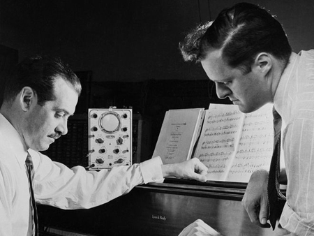
Hieronder Laurens Hammond (links) met Hanert.
En hieronder de volledige omschrijving van het instrument, zijnde de patent-tekst:
TRUMENT J. M. HANERT Nov. 5, 1963 PERCUSSION TONE MONOPHONIC ELECTRICAL MUSICAL INS 2 Sheets-Sheet 1 Filed NOV. 20, 1959 J. M. HANERT 3,109,878 PERCUSSION TONE MONOPHONIC ELECTRICAL MUSICAL INSTRUMENT Nov. 5, 1963 2 Sheets-Sheet 2 Filed Nov. 20, 1959 United States Patent 3,169,378 PERCUSSION TONE MONOPHONIC ELECTRONICAL MUSICAL lNTRUMENT John M. Hanert, Des Plaines, llh, assignor to Hammond Organ Company, Ohicago, lit, a corporation of Delawere Filed Nov. 20, 195?, Ser. No. $54,353 8 laims. (Cl. 84-l.12)
My invention relates to musical instrument oscillators and to a form of tonal intensity envelope control system which is applicable to any form of musical instrument in which tones of a sustained character are generated.
The instrument of my invention makes use of both the players hands to play but a single tone. One hand plays upon a standard keyboard to select the pitch or pitches of tones desired. The other hand operates one or more control keys, buttons, or other spring-returned devices to cause a unitary variable gain controlling device to supply an audio signal of corresponding pitch or pitches at a sustained level and to automatically produce a smooth, percussive decay intensity envelope after the control key is released but while still playing the pitch determining keys.
This may be considered as an improvement on the apparatus shown in my Patent No. 2,540,727 in which the intensity control was merely a variable gain or rheostatlike device in which the player regulated the tonal volume by the amount of movement of the auxiliary intensity control. With this device it was virtually impossible to accurately release the control in a manner which was sulficiently smooth to simulate the effect of a long and smooth percussive decay. In my present invention I have overcome this deficiency through the provision of an automatic variable gain means which of itself provides the desirable long time interval percussive decay.
My present invention also constitutes an improvement over the unitary percussion control apparatus shown in my Patent No. 2,826,659 in which the percussion tone is initiated through a non-legato style of playing of the pitch-determining keys. This, of course, entails a difiicult style of playing and has the added musical disadvantage of producing unwanted discontinuities in the music. Furthermore, there is no means to provide different kinds of intensity envelope shapes on the various individual tones as they occur within the music.
Use of this invention enables the player to instantly change the type of intensity envelope from sustained to percussion on successive tones. Both hands are used in the production of a single tone. There are no nonlegato breaks in the tone, and the player may play the pitch-determining keys in the usual sustained manner of an organ. These latter keys can only cause a note to cease sounding upon their release. They, of themselves, cannot cause a note to sound or to decay away percussively.
Thus it is the primary object of my invention to provide a novel musical instrument in which the pitches of the tones selected by one hand on a conventional keyboard are caused to sound in a sustained manner and to decay away percussively by the respective depression and release of one or more spring-returned auxiliary control keys which are operated by the other of the players hands.
A further object is to provide a novel form of monophonic musical instrument in which the-re is a pitch determining keyboard for one hand operation having switches to both tune an oscillator and cause rapid cessation of tone when all the keys are released, together with separate automatic slow decay envelope control means operable, when released, by the players other hand.
Another object is to provide such a monophonic instrument with auxiliary controls to be operated by one of the 3,ld9,8l8 Patented Nov. 5, 1963 ice 2 players hands which produce a sustained intensity envelope while held down and a percussion decay envelope after release thereof.
Another object is to provide a novel relaxation type oscillator which is tuned by resistors, is stable in operation, and has a frequency of oscillation which is very nearly directly proportional to its tuning resistor value.
Another object is to provide a vibrato means for the above oscillator which is effective to periodically vary a direct current potential which is commonly connected to all of the tuning resistors to provide a vibrato of substantially uniform width in all of the tones which may be produced.
Another object is to provide a musical instrument in which the control keys are elfective to regulate only a fraction of the total acoustic energy, thus to provide a semi-sustain feature.
Another object is to provide a novel form of oscillator which can be unitarily tuned with a variable capacitor to provide for equal frequency shifts for all the tones of the instrument.
Another obiect is to provide a novel monophonic musical instrument which may be economically manufactured in kit form and which may be connected and assembled by a novice in a relatively short period of time.
A further object is to provide an instrument having a vibrato introducing generator which is equally effective on the lower pitched tones and the higher pitched tones.
Other objects will appear from the following specification, reference being had to the drawings. in which:
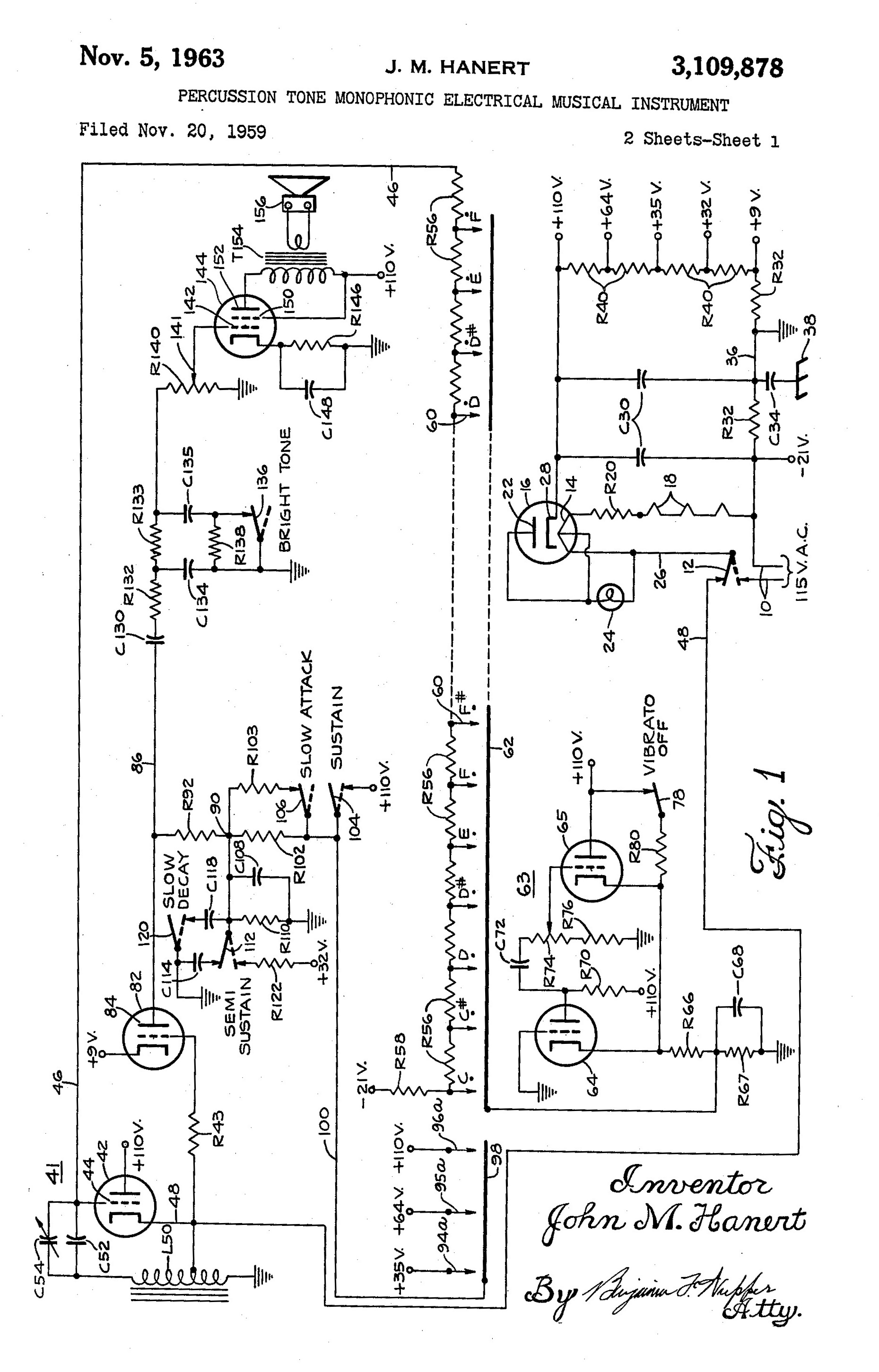
FIG. 1 is a schematic circuit diagram of the instrument; and
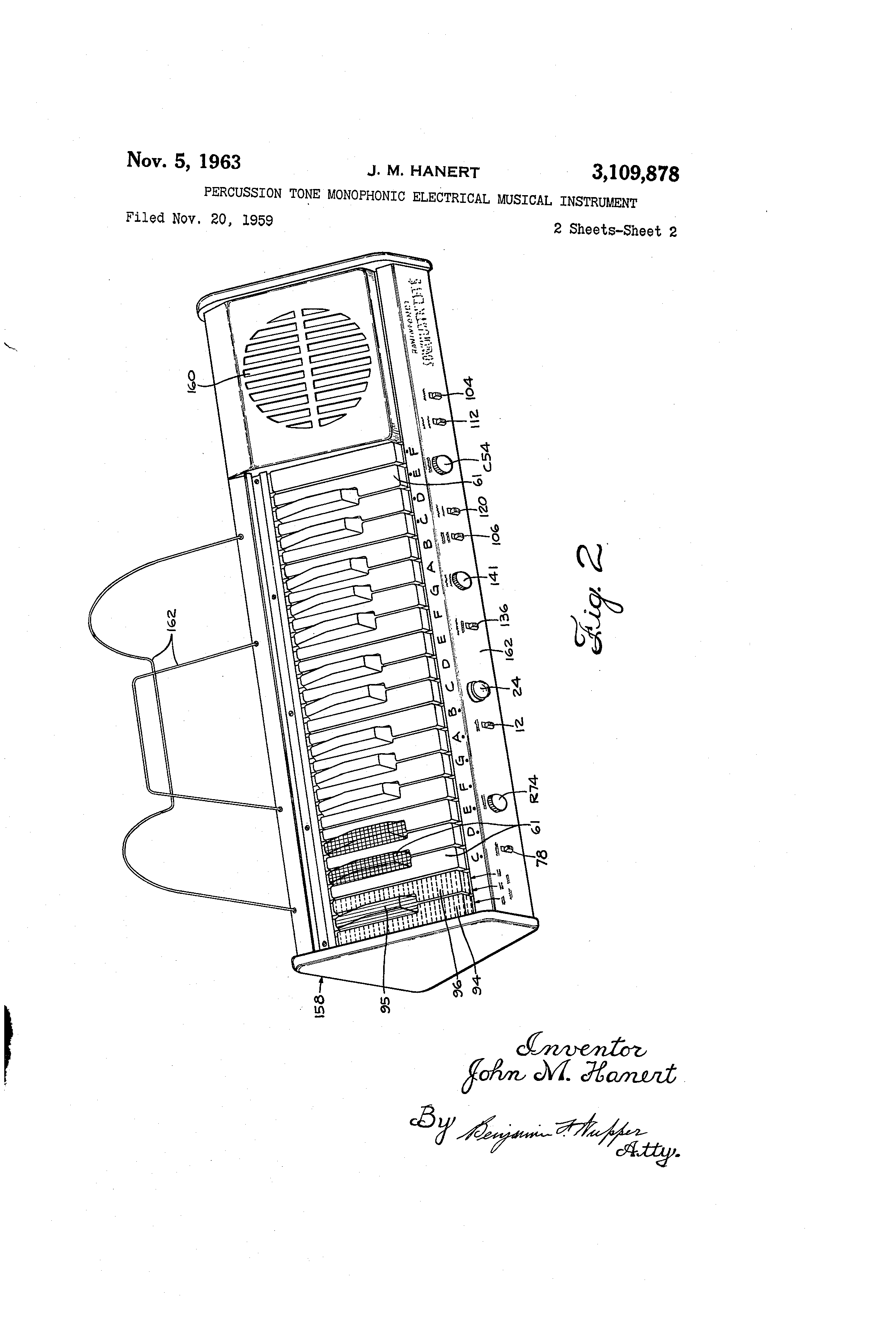
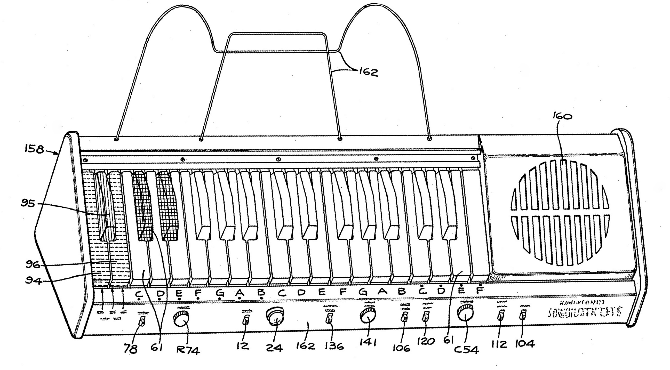
FIG. 2 is a perspective view of the instrument.
Referring to FIG. 1 the power supply comprises a pair of conductors l0 connectable to the usual 115 volt A.C. source, Upon moving a manually operated main switch 12 to its dotted line position, current is supplied to the heater 14 of a diode rectifier l6 and to the heaters 18- of the three other vacuum tubes employed in the instrument and through a voltage dropping resistor R20. The plate 22 of the diode half-wave rectifier is connected to the center of the heater 14!- and is also connected through a pilot lamp 24 to a conductor 26 connected to the fixed terminal of switch 12. The cathode 2 8 of diode 16 is connected to a v. output terminal while one of the conductors lid is connected to 21 -21 v. terminal. A pair of capacitors C36 and a pair of resistors R32 form filtering meshes together with a capacitor C34 which is connected between a conductor as and the chassis 38. The conductor 36 is also connected to ground. A series of resistors R40, together with R32, form a voltage divider and are of values to provide the voltages indicatednamely, +9 v., +32. v., +35 v., and +64 v.-on the terminals indicated by these values.
A variable frequency oscillator 41 for generating the tone signals comprises a triode 42, the anode of which is connected to the +110 v. terminal of the power supply. The grid 44 is connected to a conductor 46. The cathode of this triode is connected to the conductor 48 which is connected to the upper terminal of the main switch 12 and also to a tap on an inductance L50. One terminal of this inductance element is connected to ground while the other terminal is connected to the grid as by a fixed capacitor C2 and a variable trimming capacitor C54 in parallel therewith, which may also be used to tune the instrument to the pitch of a piano or other instrument.
The conductor 46 is connected to one end of a series of tuning resistors R56 which, from right to left, are of increasing graduated values. The left hand resistor R56 of this series is connected through a relatively low value resistor R5 to the 21 v. tenminal of the power supply. The junctions of the series of resistors R56 are connected resistor precision.
snot-tars mediate octave (shown only in FIG. 2) having merely the note designation. it will be noted that there are two octaves plus six se-mitone playing keys 61.
The output of the oscillator ill is frequency modulated by a vibrato oscillator 63 comprising triodes 64 and 6:3. The plate of triode 65 is connected to the +110 v. terminal of the power supply, while the cathodes of both triodes 64 and as are connected together and to ground through resistors R66 and R67 in series. The resistor i l resistor R43. The plate 84 to conductor 86, which is connected to a terminal W by a plate load resistor R92. The potential on the terminal 9-9 may be changed by the operation of a number of switches.
It will be noted from F162 that there are three spring returned or otherwise self-restored keys 94, 95, and 26 at the left hand end of the keyboard. These keys are distinctively colored as, for example, keys 94 and 96 being gray while the key 95 may be red. These three keys respectively operate switches 94a, 95a, and 96a also identified in FIG. 1 by their apparent pitch positions in the manual. These switches are respectively connected to terminals +35 v., l-l-64 v., and +110 v. Whenone of these R67 has a bypass capacitor C63 connected in parallel therewith. The triode 64 has its plate connected to the +110 v. terminal of the power supply through a load resistor R70 and is connected to the grid of triode 65 through a capacitor C72 and potentiometer resistor R74.
Resistor R74 is in series with a resistor R76 connected to ground. By adjustment of the potentiometer R74 the frequency rate of the vibrato may be changed through a small range from its normal frequency of approximately 7 c.p.s. By means of a manually operated switch 78 the cathodes of triodes 64, and '65 may be connected through resistor R86 to the +110 v. terminal so as to stop the operation of the vibrato oscillator.
The junction between resistors R66 and R67 is connected to the common line or bus bar 62 and acts to vary the potential upon the bus bar as the vibrato oscillator cycles. As aresult, the vibrato oscillator is equally effective at all pitches, since the potential at grid 44 is equally varied at all frequencies in a cyclical manner by operation of the vibrato oscillator.
The oscillator and vibrato circuits have the following operating characteristics. The change in potential upon the oscillator grid, and hence the frequency of oscillation, depends principally upon the time constant established by the resistors 125d and capacitors C52 and C54 and upon the potential upon the bus bar 62. In order to stabilize these operating conditions, the resistance in the plate circuit of the oscillator should be low. The inductance L50 is shown as center tapped. Even though it is not necessary, it is convenient to take the output from a tap on the inductance L59 and this tap may also be used for the cathode connection.
The output of this oscillator has a very sharp spike-like wave form with an extensive rest period between spikes, the length of the rest depending upon the time constant. Since the frequency is directly dependent upon the time constant, it bears a one-to-one relationship to the value of "the resistance R56. Thus, for instance, a change in the resistance by a value of 2.2 will result in a frequency change by a value of 2.2. This makes it very convenient in arriving at the values for the individual resistors F.5d.
Note also that the frequency precision is equal to the Thus a 10% resistor will give a certain note within a 10% variation. Furthermore, the variable capacitor C54 tunes all of the notes together and is therefore a convenient arrangement for tuning the instrument to other instruments of fixed pitch. a
The vibrato oscillator determines the instantaneous potential of the bus bar 62 and thus the instantaneous pitch of the note or notes played. As the vibrato oscillator passes through its cycle of operation, therefore, all notes played will be frequency modulated.
This quite simple oscillator circuit and the combined oscillator-vibrato circuit have proved to be very stable in operation, and the components can be provided at relatively low cost.
Anamplitude control triode 52 has its cathode connected to the +9 v. terminal of the power supply, while its grid is connected to the cathode of triode 42 through a switches is closed by operation of its associated key 94, 95, or as, the potentials indicated will be impressed upon a bus bar 98 which is connected by a conductor 100 and resistor R162, and normally also through a resistor Rlilit, to the terminal d6.
Thus, plate current at a selected potential is supplied to the triode 32. Upon depression of the key94- a 35. volt potential (less the voltage drop across resistors R102 and R103) is impressed on. the terminal NP and the output of.
The triode 32 will be of low amplitude and the tone pro duccd will be soft. Similarly, when the key 95 is-depressed, approximately a 64 volt potential will be impressed on the terminal @113 and the output of the triode will be of medium amplitude. When the key 96 is depressed the potential of approximately volts will be impressed on the terminal 90, with the result that the output of the triodc 82; will be of high amplitude.
The potential on the terminal 90 rises at a controlled rate because of the fact that there area number of resistors and capacitors which may be switched into the circuit to provide an adjustable tone intensity envelope controlling mesh.
If it is desired that the tones shall be of a sustained character, a sustain switch 104 is closed so as to connect the terminal 9a to the +110 v. terminal through the resistors R1 2 and R1il3. Under this condition, operation of one of the playing keys 61 will result in causing the control tube 8?. to transmit the signal from the oscillater 41 at high amplitude, and such transmission will continue as long as the playing key is held depressed.
When a slow attack switch 186 is opened the resistor R103 is effectively removed from the circuit and the 7 be connected to ground by a switch H2 and capacitor.
C114. when the semi-sustain switch 112 is in its full line position. The terminal may also be connected to ground througha capacitor C118 When a slow decay switch 12-8 is in its dotted line position. When the switch 112 is in dotted line position, the terminal hit is connected to the +32 v. terminal .by a decay resistor R122, to produce low amplitude semi-sustained tones.
It will therefore be apparent that the rate at which the potential at the terminal'9tl will rise and fall upon closing andopeningone of the switches 94a, sea, or 96a will depend upon the positions of the switches 164,166, 112, and
12d' The value of the resistor R133) is low relative to.
pacitors Clihl, C114, and C113 as are effective, depending on the positions of switches 112 and 12%.
When switch 104- is closed, operation of the playing keys will cause the production of sustained organ-like tones, and operation of any of the keysQd, 9f, and 96, will not have any useful effect.
of the triode 82 is connected snoasvs *When switch 106 is open with the switches 104, 112, and 120 in the full line positions, the tone sounded upon depression of the playing keys will have a slow attack and a normal decay, the decay portion of the tone intensity envelope being determined by the exponential discharge of capacitors C114 and C168 through resistor R1115.
When switch 120 is closed, the capacitor C113 is connected in parallel with capacitors C193 and C114, and will render the decay portion of the tone intensity envelope to be of greater duration.
When switch 112 is in its dotted line position, it will be clear that the terminal 90 is connectedto the +32 v. terminal through resistor R122 and thus the tones will be sounded at low intensity and will be sustained as long as the playing key is held depressed. When the key is areleased, the decay of such sustained tones is determined by the rate of discharge of capacitor C108 and also C118 if switch 120 is in its dotted line position, such discharge taking place through resistor R116.
The plate 84 of the triode 82 is connected by conductor 86 and blocking capacitor C131 to a high harmonic attenuating filter comprising series resistors R132 and R133. The terminals of resistor R133 are connected to ground through capacitors C134 and C135, provided a bright tone switch 136 is in its full line position. An antistatic charge resistor R138 is connected across the switch 136. When switch 136 is open, the capacitor C134 is the main path by which the high harmonics may be passed to ground and the tones transmitted through this mesh will be brighter; that is, contain harmonics of higher amplitude than when this switch is closed. The signal, as modified by this bright tone mesh, is impressed across a potentiometer R141) serving as a volume control. The movable contactor 141 of this potentiometer is connected to the control grid 14?. of a tetrode 144. The cathode of this tube is connected to ground by a self-bias resistor R146 and a bypass capacitor C148. The screen grid 150 is connected to the +110 v. terminal while the plate 152 is connected to the same terminal of the power supply through the primary winding of an output transformer T154, the secondary of this transformer being connected to the speaker 156.
Referring to FIG. 2, the instrument is mounted in an elongated case 158 which includes the speaker gnille 160 and sheet music rack 161. The various manually operable controls are mounted on a front rail 162. For convenience, the manually engageable parts of the switches and the like have applied thereto the same reference charactors as used in describing their electrical parts shown on the circuit diagram of FIG. 1. The playing keys 61, aswell as the tone intensity keys 94 as, and 96, are mounted at a downwardly sloping angle for convenience in playing and to provide sufiicient space beneath them for the various electronic components without making the case unnecessarily high.
The instrument may, of course, be played in a number of different ways depending upon the setting of the various controls, but in general the player will play the solo part on the manual keys 61 for the rendition of a solo part of a composition. When the playing key 61 is depressed, the player operates one of the keys 94, 95, or 96, depending upon whether he wishes the tone to be sounded soft, medium, or loud. If a note is repeated, the player need merely hold the playing key depressed while repeating the operation of one of the three tone control keys 94, 95, or 96.
It will be recalled that when the main power switch 12 is moved from its dotted to its full line position, it connects the cathode of oscillator triode 4 2 to ground, the circuit being completed through the heater 14 of the diode 16, resistor R20, and the heaters 18 of the three other triodes employed in the instrument (it being understood that the triodes 42 and 82 are in the same envelope, as are also triodes 64 and 65'), and resistor R32, and thus immediately stops oscillation. If the oscillator cathode were not connected to ground immediately upon opening the power switch 12, there might be a tendency for the oscillator to emit spurious signals, due mainly to residual charges which may be present in some of the capacitors.
It is important to note that the tone oscillator frequency is altered as a direct function of the resistor R56 change, as a direct function of the capacitor C52 and C54 change, and as a direct function of the change in potential of the grid voltage as supplied by the vibrato oscillator. Thus, the overall tuning can be altered by adjusting C54, and the overall tuning can be frequency modulated by the vibrato oscillator without changing the tuning between notes as established by the resistors R56.
In playing the instrument the musician will normally set the volume control potentiometer R to a certain position so that the amplitude of the tone signals will be suitable for the size and acoustic nature of the enclosure in which the instrument is being played, and will seldom change the setting of this potentiometer during the course of playing a selection, but instead will utilize the tone control keys 9 1', 95, and 96 selectively to vary the intensity of the output tone.
While I have shown and described a particular embodiment of my invention, it will be apparent to those skilled in the art that numerous modifications and variations may be made in the form and construction thereof, without departing from the more fundamental principles of the invention. I therefore desire, by the following claims, to include within the scope of my invention all such similar and modified forms of the apparatus disclosed by which substantially the results of the invention may be obtained by substantially the same or equivalent means.
I claim:
1. In an electrical musical instrument of the melody type comprising an oscillator including an electron discharge device the grid potential of which determines its frequency of oscillation and having a manual comprising a plurality of playing keys and a tone amplitude controlling key, a source of relatively low potential of such value as will cause the oscillator to stop oscillating when impressed upon the control grid of the oscillator tube, a point of relatively fixed potential of such value that when impressed on the control grid of the oscillator tube will cause the later to oscillate at high frequency, the combination of a plurality of resistors connected in series between said low potential source and the grid of said oscillator tube, a junction connected to said point of fixed potential, a plurality of switches actuated by said playing keys each having one pole connected to one of the connections between successive resistors of said series of resistors, the other poles of said switches being connected to said junction, an amplifying electron discharge device having its input coupled to the output of said oscillator and having a terminal connected to one of its electrodes, the potential at said terminal being determinative of the amplitude of the output of the amplifying electron discharge device, and switch means operated by said tone amplitude controlling key effective when actuated to impress a potential upon said terminal, the last said potential being sufficient to produce an output from said amplifying device.
2. In an electrical musical instrument of the melody type comprising an oscillator including an electron discharge device the grid potential of which determines its frequency of oscillation and having a manual comprising a plurality of playing keys and a number of tone amplitude controlling keys, at source of relatively low potential of such value as will cause the oscillator to stop oscillating when impressed upon the control grid of the oscillator tube, a point of relatively fixed potential of such value that when impressed on the control grid of the oscillator tube will cause the latter to oscillate at high frequency, the combination of a plurality of resistors connected in series between said low potential source and the grid of said oscillator tube, a terminal, switch means connecting said terminal to said point of relatively fixed potential, a plurality of switches actuated by said playing keys each having one pole connected to one of the connections between successive resistors of said series of resistors, the other poles of said switches being connected to said terminal, an amplifying electron discharge device having its input coupled to the output or" said oscillator and having a terminal connected to one of its electrodes, the potential at said terminal being determinative of the amplitude of the output of the amplifying electron discharge device, and switches operated by said tone amplitude controlling keys effective selectively to impress different potentials upon the last sai terminal.
3. in an electrical musical instrument of the melody type having electroacoustic translating means and an oscillator including an electron discharge device the grid potential of which determines its frequency of oscillation and having a manual comprising a plurality of playing keys, a source of relatively low potential or such value as will cause the oscillator to stop oscillating when impressed upon the control grid of the oscillator tube, a point of relatively fixed potential of such value that when impressed on the control grid of the oscillator tube it will cause the latter to oscillate at high frequency, a plurality of resistors connected in series between said low potential source and the grid of said oscillator tube, a bus connected to said point of fixed potential, a plurality of switches actuated by said playing keys each having one pole connected to one of the connections between successive resistors of said series of resistors, the other poles of said switches being constituted by the said bus bar, tone intensity envelope control means connected between the oscillator and the translating means including a terminal, the potential of which determines the amplitude of the tone signal transmitted to the electroacoustical translating means, a storage capacitor connected between said terminal and a source of relatively fixed potential, an auxiliary spring return envelope determining means manually operable to cause a change in the potential on said capacitor so as to produce a high intensity output signal, and further potential changing means operable two of itselectrodes with one of said electrodes being connected through a portion of said coil to a neutral voltage source, a plurality of serially connected resistors con-t nected directly from said capacitor and the other electrode to a negative voltage source, and means for selectively interconnecting the junction of respective ones of said resistors to a third voltage source more positive than said negative source for enabling said valve to conduct at a frequency dependent on the time constant of said capacitor and the resistance value of the resistors connected between said capacitors and said third voltage source.
5. in the oscillator claimed in claim 4, a last source of direct current potential, means for cyclically varying said direct current potential and applying said cyclically varying direct current potential to the junction of any one of said resistors to vary the frequency at which said valve conducts in accordance with said varying direct current potential irrespective of said resistance value.
6. The oscillator claimed in claim 4 in which said valve has a third electrode connected directly to a source of potential.
7. For use with the oscillator claimed in claim 4, a
second valve connected to said one electrode for amplifying the voltage change at said electrode, a plurality of different potentials, means for selectively applying any one of said diiferent potentials to said second valve for controlling the amplification provided by said second valve, and means for automatically terminating the application of any one of said different potentials to said amplifying device at a predetermhied rate to provide a preselected tone envelope for any frequency amplified by said second valve.
8. A tone generating arrangement for use in an organ, the improvement comprising a resistance tuned relaxation oscillator, a normally ineffective amplifier connected to said oscillator for amplifying the output thereof only when rendered effective, and repetitively operated amplitude selection means for rendering said amplifier eifective only on each repetitive operation to amplify the output of said oscillator to any one of a plurality of different amplitudes.
References Cited in the file of this patent UNITED STATES PATENTS OTHER REFERENCES The Solovox, Electronic Engineering, pages 275-278,